Lately I have been thinking about getting a low-resolution image sensor for some bare-metal project prototyping, and I was disappointed by the limited availability of low-cost low-resolution camera modules. I wanted parts in the price range of a few bucks, not a few dozen bucks. I then remembered of a bunch of old computer parts I had stored, which includes pieces of an old laptop. The laptop had a webcam, so I decided to try reverse-engineering the module and see if I could do anything with it.
The laptop
The parts mentioned above are from a Hyundai P57V laptop from about 2003. Equipped with a Pentium IV processor running at 2.8 GHz, 512 MB memory, an ATI Radeon 9000 GPU with 64 MB of dedicated memory, a 15” 1400x1050 display, 40 GB mechanical drive storage, it used a Clevo D470 chassis and came with Windows XP pre-installed. Another interesting feature was the presence of an integrated webcam, which at the time was not commonplace.1
Today most people will probably not recognise Hyundai as a computer brand, and it was a niche brand even back then. Despite of that, however, at the time this model was actually a high-end (and relatively expensive) laptop, with good raw specs targeting power users. The main drawbacks were weight (~3 kg), bulkiness, and low battery life (about one hour), which at the time qualified it as a desktop-replacement machine rather than a true portable device.
This was my first laptop, having used and owned only stationary/desktop computers before it, and I have some fond memories of it. It carried through a lot of schoolwork and at the same time it was an amazing learning platform. It has probably been the single most influential electronic device in my personal competence development.
Besides the aging compute power during the fast-paced development of consumer electronics in the 2000s, and some transient problems with the power circuit that drove me to get a replacement, what finally sent the laptop to retirement was the fact that its plastic chassis had completely broken down.2 I did not however throw it away, but I rather stored it, partly for memory and partly as future tinkering material.
The webcam
Fast forward by many years. Remembering of the old laptop parts, I located the box where I kept them stored and fished out the webcam.
The webcam module has an elongated PCB, with the camera module proper (sensor chip and lens assembly) in the middle, and two wings of circuitry around it, covered by an RF shield (the silver-coloured sheet wrapping the PCB).
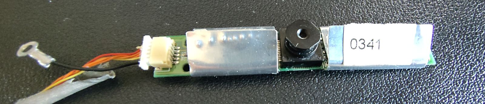
The 0341 marking on the RF shield looks like a date (2003 week 41), which
would be consistent with the time of manufacturing.
The connector is interesting, as it has five wires running inside a fabric sheath without shielding, of which one (black with a ring connector) is obviously GND. Putting the PCB under the digital microscope and looking at the connector, it can be seen how the yellow wire is directly connected to the black one, so that has also to be GND.
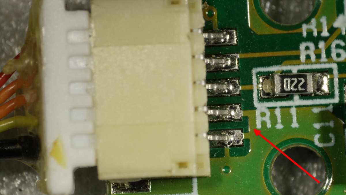
Therefore one of the remaining wires has to be the VCC, likely the red one, and the remaining two orange wires are probably data lines. I therefore started suspecting it might be a USB connection with non-standard wire colours, where the orange wires would be the D+ and D- (being twisted together is another clue, as USB uses differential signaling for the data line).
This could be enough information already to experiment with a USB connection, but I wanted to gather more information before trying anything physical. I removed the RF shield to take a look at the ICs on the PCB and took a couple more pictures of the top side under the microscope. From a cursory look, the left side of the PCB is probably mostly wiring and USB PHY front-end:
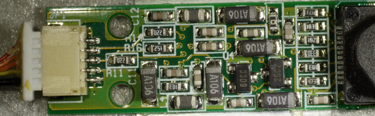
The two data wires go straight into
SMDs, the two marked
as 220 are probably resistors (used for impedance
matching on USB D+ and D-
lines) and 152 might be a pull-up resistor on the D+ line (which would denote
a full-speed USB device).
The right side is more interesting:
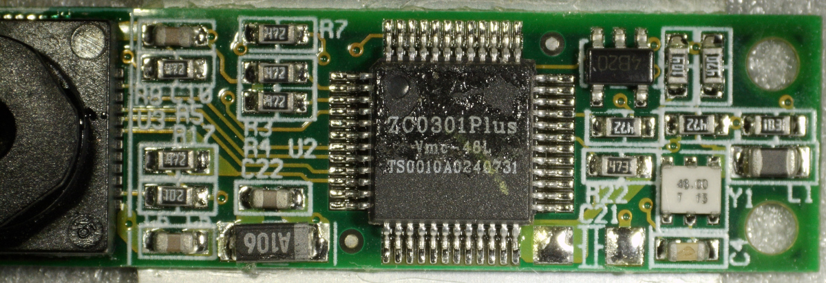
The big IC in the middle, easily identifiable by its marking, is a ZC0301Plus USB camera controller by Vimicro (from 2002). So this confirms the theory of USB connection. Looking at the datasheet we can get some general features:
- 3.3V input power
- 15 fps VGA
- USB 1.1 controller
- 8-9 bit raw Bayer input
- A programmable ISP
- JPEG compression
- Parameters programmable via EEPROM interface3
Other outstanding ICs are a 48 MHz oscillator (marked as 48.00), which
is consistent with USB 1.1, and a
SOT-23-5 package
(marked as 4B20) which is a prime candidate for a voltage regulator (as I
have not yet seen a buck converter nor other circuitry that might be performing
the step-down from the 5 V USB VCC to the 3.3 V expected by the
controller).
The back reveals part of the wiring and has a few markings on it:
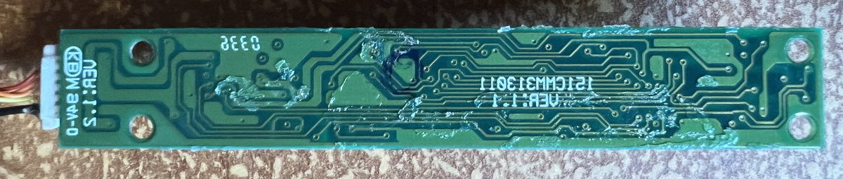 Mirrored image (to simplify comparison with images of the PCB's front).
This is however not as informative. The main marking 151CMM313011 turns out
to be the part number of a webcam module used in Clevo D470 laptops,4 for
which no documentation is readily available online. Other markings are the
fire-retardant rating KEM
94V-0 and what looks like another date (0336, probably 2003 week 36).
Connection
Being now sure about the interface, I wanted to connect the camera and see if I could make it work. The upside of USB is that I could try direct connection to a PC without needing much upfront implementation work of the physical layer. I would only need to possibly implement a working driver. The downside is that USB requires a complicated software stack, so it is sub-optimal for some of the bare-metal projects I had in mind (but I might still be able to work with it).
I cut off the end connector of the outgoing cable, crimped JST-XH female pins to the wires, and put them in a female connector. I did the same with an old USB cable, cutting a piece of cord ending with a USB A connector and crimping another female JST-XH connector to it.5
Note that there is still an unknown variable, as I cannot tell apart the D+ and D- wires yet, being of the same colour.6 Flipping the two data wires is not dangerous but it will result in a device that will not enumerate, so I can just try guessing at first, and if it does not work I can try swapping the wires.
Plugging in the USB and having a look at the kernel message buffer:
$ sudo dmesg
...
[  806.730641] usb 1-1.4: new full-speed USB device number 4 using xhci_hcd
[  806.730719] usb 1-1.4: Device not responding to setup address.
[  806.934346] usb 1-1.4: Device not responding to setup address.
[  807.137562] usb 1-1.4: device not accepting address 19, error -71
[  807.137846] usb 1-1.4: WARN: invalid context state for evaluate context command.
[  807.138168] usb 1-1-port4: unable to enumerate USB device
Not good. The device is enumerating, and we see it being recognized as full speed,7 but it seems to not respond properly. The connection is probably too noisy. After checking and steadying the connector:
$ sudo dmesg
...
[ 5422.650056] usb 1-1: new full-speed USB device number 5 using xhci_hcd
[ 5422.788583] usb 1-1: New USB device found, idVendor=0ac8, idProduct=301b, bcdDevice= 1.00
[ 5422.788618] usb 1-1: New USB device strings: Mfr=1, Product=2, SerialNumber=0
[ 5422.788634] usb 1-1: Product: PC Camera
[ 5422.788647] usb 1-1: Manufacturer: Z-Star Corp.
[ 5422.794321] gspca_main: gspca_zc3xx-2.14.0 probing 0ac8:301b
[ 5423.033932] input: gspca_zc3xx as /devices/pci0000:00/0000:00:14.0/usb1/1-1/input/input41
That is better. And, good news, there seems to be a supported driver
(gspca_main) in the Linux kernel, and we now know vendor and product id. We
can confirm with lsusb:
$ sudo lsusb -v -d 0ac8:301b

Bus 001 Device 005: ID 0ac8:301b Z-Star Microelectronics Corp. ZC0301 Webcam
Negotiated speed: Full Speed (12Mbps)
Device Descriptor:
  bLength                18
  bDescriptorType         1
  bcdUSB               1.10
  bDeviceClass          255 Vendor Specific Class
  bDeviceSubClass         0 [unknown]
  bDeviceProtocol         0
  bMaxPacketSize0         8
  idVendor           0x0ac8 Z-Star Microelectronics Corp.
  idProduct          0x301b ZC0301 Webcam
  bcdDevice            1.00
  iManufacturer           1 Z-Star Corp.
  iProduct                2 PC Camera
  iSerial                 0
  bNumConfigurations      1
  Configuration Descriptor:
    ...
Device Status:     0x0000
  (Bus Powered)
The device class being vendor specific might not sound ideal, as it means that
the camera uses some non-standard protocol as opposed to a standard USB video
device class (UVC)8
and therefore might require more integration work. It is not necessarily as bad
as it sounds however, considering that such an old camera is likely to use a
simpler protocol than UVC itself, and also the gspca_main driver already has
an open-source implementation that can be used as a reference.
We can check what output formats are supported:
$ v4l2-ctl -d /dev/video2 --list-formats-ext

ioctl: VIDIOC_ENUM_FMT
        Type: Video Capture

        [0]: 'JPEG' (JFIF JPEG, compressed)
                Size: Discrete 320x240
                Size: Discrete 640x480
Only JPEG, and this checks out with what we gathered from the datasheet. We can also verify what parameters can be user-controlled:
$ v4l2-ctl -d /dev/video2 --list-ctrls

User Controls

                     brightness 0x00980900 (int)    : min=0 max=255 step=1 default=128 value=128 flags=slider, 0x00001000
                       contrast 0x00980901 (int)    : min=0 max=255 step=1 default=128 value=128 flags=slider, 0x00001000
                          gamma 0x00980910 (int)    : min=1 max=6 step=1 default=4 value=4 flags=slider, 0x00001000
                 gain_automatic 0x00980912 (bool)   : default=1 value=1 flags=0x00001000
           power_line_frequency 0x00980918 (menu)   : min=0 max=2 default=0 value=1 flags=0x00001000
                      sharpness 0x0098091b (int)    : min=0 max=3 step=1 default=2 value=2 flags=slider, 0x00001000

JPEG Compression Controls

            compression_quality 0x009d0903 (int)    : min=50 max=87 step=1 default=75 value=75 flags=0x00001000
Sensor
So far, none of the information we read from the device offers any clue on what sensor the camera uses. There are no obvious markings, and I did not intend to disassemble the camera module to try accessing the sensor chip directly (installed under the lens assembly), which would likely be a permanent one-way operation, probably destructive towards the rest of the PCB.
So I decided to have a look at the source code of the driver in the Linux kernel source tree to look for a lead. Grepping for the vendor/device id quickly brought me to drivers/media/usb/gspca/zc3xx.c, where I can see the device model
static const struct usb_device_id device_table[] = {
    ...
	{USB_DEVICE(0x0ac8, 0x301b)},
    ...
Looking around at the definition of the
sd_init
function, which is called by struct usb_driver::probe to initialize the
sub-driver, we can see a switch over the sensor types, where each case has a
gspca_dbg macro that logs the sensor model.
static int sd_init(struct gspca_dev *gspca_dev)
{
    ...
    switch (sensor) {
		case -1:
			switch (sd->sensor) {
			case SENSOR_MC501CB:
				gspca_dbg(gspca_dev, D_PROBE, "Sensor MC501CB\n");
                ...
Enabling debug should add those prints to the kernel message buffer. A quick
look at the kernel module info shows how it accepts a debug parameter.
$ modinfo gspca_main
filename:       /lib/modules/6.18.20-1-lts/kernel/drivers/media/usb/gspca/gspca_main.ko.zst
version:        2.14.0
...
parm:           debug:1:probe 2:config 3:stream 4:frame 5:packet 6:usbi 7:usbo (int)
Reloading the driver with a suitable debug level gives the desired information:
$ sudo modprobe -r gspca_zc3xx gspca_main
$ sudo modprobe gspca_main debug=7
$ sudo modprobe gspca_zc3xx
$ sudo dmesg
...
[ 7978.969572] usb 1-1: new full-speed USB device number 13 using xhci_hcd
[ 7979.101098] usb 1-1: New USB device found, idVendor=0ac8, idProduct=301b, bcdDevice= 1.00
[ 7979.101111] usb 1-1: New USB device strings: Mfr=1, Product=2, SerialNumber=0
[ 7979.101118] usb 1-1: Product: PC Camera
[ 7979.101124] usb 1-1: Manufacturer: Z-Star Corp.
[ 7979.102443] gspca_main: gspca_zc3xx-2.14.0 probing 0ac8:301b
[ 7979.336696] gspca_zc3xx 1-1:1.0: probe sensor -> 000c
[ 7979.336714] gspca_zc3xx 1-1:1.0: Find Sensor ICM105A
[ 7979.337305] input: gspca_zc3xx as /devices/pci0000:00/0000:00:14.0/usb1/1-1/input/input53
[ 7979.340156] gspca_zc3xx 1-1:1.0: video2 created
[ 7979.340178] gspca_zc3xx 1-1:1.0: found int in endpoint: 0x82, buffer_len=8, interval=10
[ 7980.499089] gspca_zc3xx 1-1:1.0: try fmt cap JPEG 320x240
[ 7980.504396] gspca_zc3xx 1-1:1.0: try fmt cap JPEG 320x240
The chip is an ICM105A, a CMOS
sensor from 2001 by IC
Media Corporation, a no longer operating Taiwanese company. From the
datasheet
we can extract some of the main features:
- Single 3.3 V power supply
- 307,200 (640x480) pixels, VGA format, used with 1/4” optical system
- Up to 30 fps
- 8-bit raw output with a standard Bayer pattern
- I2C control interface
- On-chip 9-bit ADC
Testing
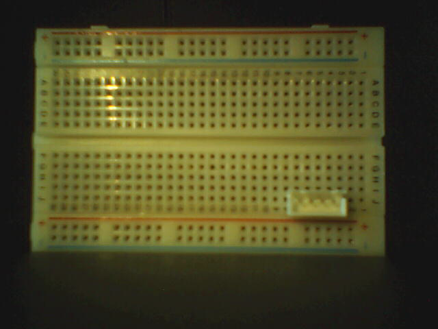
With the camera connected, I can now capture some test images. Using a breadboard as a test target:
With different light and angle:
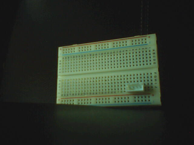
These definitely look like images from non-professional consumer-grade electronics from 20+ years ago. Besides obvious low resolution and noise, we can see the limits of its range and exposure control. These limitations however will make it even more interesting to see what can be done when trying to push a device like this to the edge by using it as input source for computer vision and signal processing.
Power
One unanswered question is how and where power is converted from 5V (USB) to
3.3V (microcontroller and image sensor). The main candidate so far has been the
IC marked as 4B20, a SOT-23-5 package installed besides the microcontroller.
This seems to be consistent with the wiring, and now that the camera is powered and working I can confirm it by measuring the voltage on the pins:
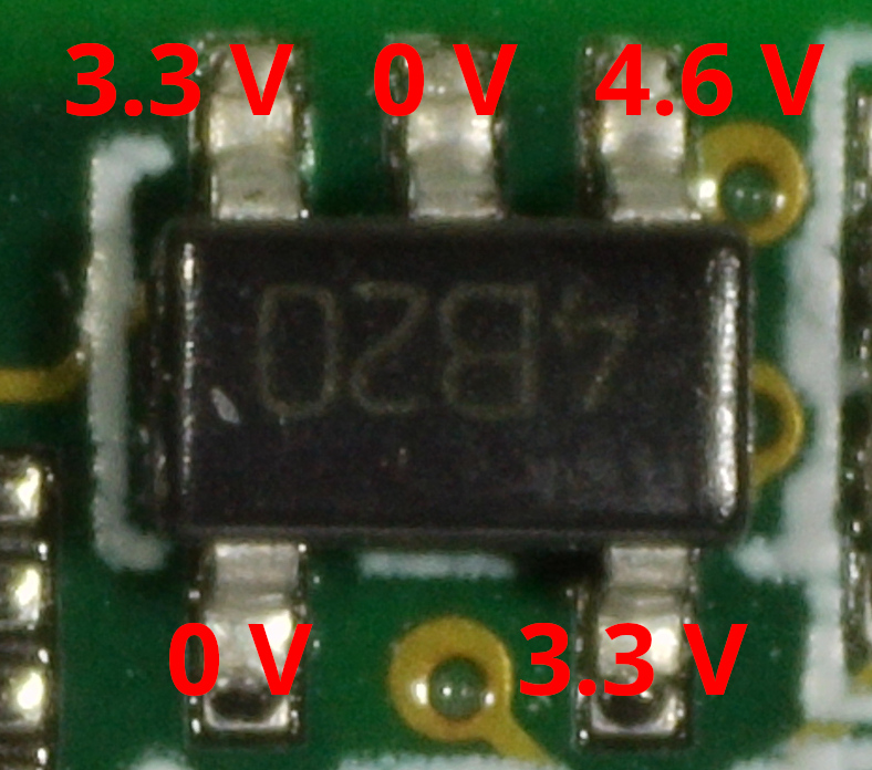
This is consistent with what I would expect from a linear regulator. The three pins on the upper side are likely enable pin (3.3 V), ground (0 V), and input (~4.6 V, lower than 5 V probably due to input loss), while the two pins on the bottom are likely a noise pin (0 V) and the output (3.3 V). This layout is compatible with linear regulators from the time (like the Micrel MIC5205 or the Toshiba TAR5SBxx, of which this might have been a clone).
I was also interested in understanding power consumption, so I first measured the voltage on the input pin right out of the USB connector (4.6 V, so consistent with the readout from the linear regulator), and then I read the input current:
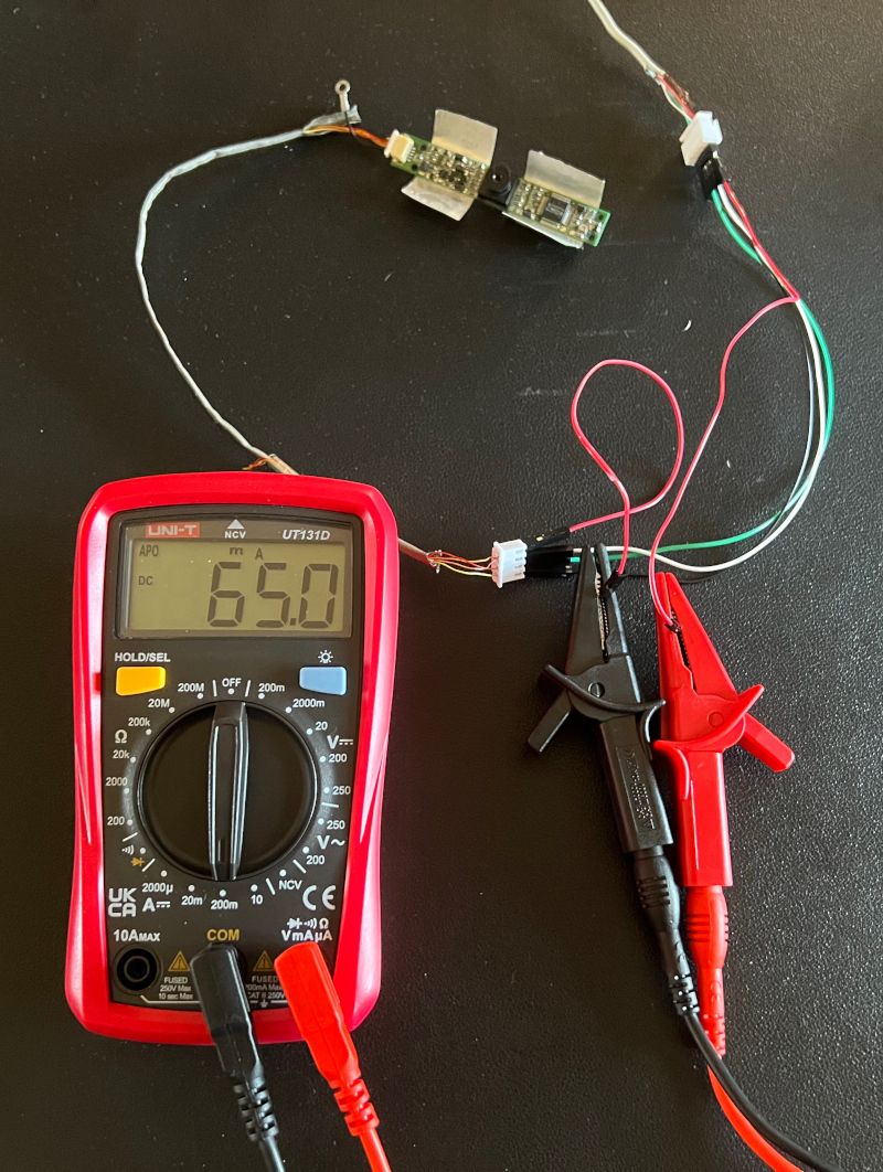
The reading was of ~10 mA when idle, and 65~70 mA when recording in video mode,9 corresponding to
\[10~\text{mA} \cdot 4.6~\text{V} \approx 46~\text{mW}\]in idle and
\[70~\text{mA} \cdot 4.6~\text{V} \approx 322~\text{mW}\]when recording. This measured power usage is surprisingly low compared to modern webcams, I was expecting to see higher values, considering how little power efficient devices were at the time compared to today. The result is easy to interpret though as, compared to modern devices, this camera module has much lower resolution, lower frame rate, and minimal on-board ISP, so the lower power usage is due to the sheer low volume of operations and calculations rather than any power efficiency aspect.
Conclusions
This was a quick fun dive in the past. Starting from an anonymous laptop module with only a few PCB markings, it allowed reconstruction of chipset, sensor, wiring, USB interface, and power requirements. I then managed to connect it to a modern PC and get it in working order.
The task was definitely simplified by the presence of a working Linux driver, meaning I did not have to also implement a kernel module in order to get it working, and it is a testament of how good Linux hardware compatibility lasts with time.
I am not sure yet if this piece of hardware will be a good fit for some of the projects I have in mind, as it requires a USB stack for connection, which is a large and complex dependency for the minimal bare metal experiments I was planning to make. But it surely remains an interesting item to experiment with.
Footnotes
-
Indeed I remember no one else having one, among the few laptop-owners in my circle at the time. ↩
-
This seems to have been a common issue, as I noticed it frequently in pictures of used Hyundai P57 laptops. ↩
-
However, no EEPROM chip is obviously visible on the PCB. ↩
-
Hardly a surprise, considering that Hyundai ImageQuest laptops were based on Clevo models. ↩
-
Having two female connectors allows me to either directly connect them to each other (using a male connector for PCB-mount as a joint), or to connect both of them to a breadboard (using two male sockets), or connecting the two cables with each other using DuPont jumpers if I want to attach measurement instruments on some of the wires. ↩
-
I could have told them apart if I unsheathed the cable and unwrapped the two orange wires, and then made an assumption based on the wire ordering in the PCB and the presence of what looks like a pull-up resistor. But I did not want to remove the cable from its sheath (yet). ↩
-
Which, for USB 1.1, means 12 Mbps. ↩
-
This is hardly surprising, considering that this camera module is older than the UVC specification itself. ↩
-
Using it as a webcam in a Proton Meet call. ↩